Satellite Antenna Upgrade at the GCARC Clubhouse
The clubhouse satellite station has had steady incremental
upgrades over the past few years but one factor had remained constant – the
antenna and rotator system. The antennas were 1980’s style Cushcraft units that
were probably average at the time and gave reasonable but not outstanding
performance. Since “outstanding” is a goal of the Skunkworks team we were able
to procure through a club member donation a pair of M2
state-of-the-art satellite antennas – the 42-element 436CP42UG crossed yagi for 70 cm and the 22
element 2MCP22 crossed yagi for 2 meters along with the fiberglass boom to
connect them. These are the top of the line satellite antennas from M2
and promised to significantly improve clubhouse satellite operations.

Figure 1 - Original Antennas
Both antennas are 18 feet long and have considerable gain
and would be a significant improvement over the existing antennas but the
additional length created potential problems in clearing the clubhouse roof and
the guy wires for the 6 meter beam so some initial planning was necessary
before the antennas arrived. Al KB2AYU did some initial measurements from the
roof of the clubhouse and concluded that the mast for the antennas needed to be
lengthened to provide enough clearance so he obtained a length of pipe of the
correct length. He and Frank N3PUU were able to remove the old antennas and
rotator from the mast and string new hardline and rotator cables to the tower
before the new antennas were completed.

Figure 2 - Al
checking antenna-to-roof clearance

Figure 3-Frank and Al removing old antennas
The new antennas required significant assembly – 42 elements
is a LOT of building, especially when a milometer of error can blow the
efficiency of the antennas. Al painstakingly assembled each section of both
antennas, carefully measuring each element to be sure that it was inserted
correctly. In most yagi antennas the director elements decrease in length along
the boom, but in these antennas a director might be longer than the previous
element so each element needed to be carefully measured down to 1/16 inch. And
two elements weren’t cut to the specified length so Al had to build them from
other materials. To make it even more difficult the assembled antennas were 18
feet long in three 6-foot sections so they couldn’t be completely assembled in
the clubhouse – they had to be finished off outside along with the vertical
elements of the 2 meter antenna that wouldn’t fit out the clubhouse door if
assembled. Frank and Al assembled the sections outside using aluminum grease.

Figure 4-Assembled antennas ready for mounting
Finally the antennas were
assembled and sitting on sawhorses outside of the shed. At that point Frank and
Al noticed that the pre-drilled holes for the mounting plate provided by M2
would align that plate in line with the antenna elements, destroying
their directivity. That problem was even
noted in the assembly directions, which advised that the assembler could drill
his own holes if he didn’t like it. The problem, of course, was that drilling a
perfectly-centered hole through a pipe resting on sawhorses is pretty difficult
so Frank designed and 3D-printed a drilling jig that would fit over the mast,
lock into the existing holes and provide guide holes for a perfectly-aligned 45
degree mounting plate. There seems to be no problem that Frank can’t solve with
his back-yard machine shop.
Once that was done it was
time to mount them, but there’s no way that antennas of that size could be
mounted without a bucket truck. Fortunately new GCARC member Dave KB3VEQ had
shown up at Field Day with his own bucket truck and was willing to bring it out
for this project. (Any ham who owns a bucket truck should never have to buy
beer again…) Dave mounted the rotator, ran the boom thru the elevation rotator and
then fastened each antenna to the end of the boom. He then connected the cables
to the rotator and antennas – and we thought we were ready to go. Not so fast…

Figure 5-Dave mounts
the rotator
The test needed one guy in the clubhouse (me) with an HT to rotate the antennas on command of the guys who were outside. After searching thru all of our clubhouse gear we were able to scrounge up a couple of HTs (what kind of hams don’t all have HTs hanging from their belts???) and we were ready for the test. I was given the command to raise the elevation of the antennas, which was followed almost immediately by the command “STOP!”. Walking outside and looking up I saw the antenna array pointing 10 degrees – towards the ground! We had carefully executed each step – except for figuring out which side of the boom the antennas should face. Obviously the boom rotates horizontally in the elevation rotator with one side rising and the other side falling, and we had the antennas facing to the falling side.
Amidst laughter, groans and trying to figure out geometry with our fingers we instructed Dave to remove the antennas and replace them at different ends of the boom. And our frustration was compounded when that arrangement ALSO aimed the antennas into the ground. That prompted another round of drawing geometric shapes in the air with KB2AYU, K2QA, N3PUU and WB2MNF all thinking that they had finally figured out the right way to orient the antennas so that they would point up instead of down. The third time was the charm, with the antenna finally rising in accordance with the rotator controller. The new cable arrangement required longer coax connections between the antennas and the hardline so Al made them overnight and installed them a day later. At that point things looked really good and I was able to make a few contacts on subsequent satellite passes.

Figure 6-Groundhog
DX
In the following couple of
days I did some testing from home using the new antennas (connecting thru the
VPN to the rotator and SDR servers) and found that the 70 cm antenna was much
improved but the 2 meter antenna wasn’t performing well. So I went out to the
clubhouse and found that the 2 meter antenna has slipped on the boom and was
now facing at about 45 degrees above the desired elevation. Aligning the
antennas with the clubhouse roof and climbing up onto the roof I was able to
push it back into alignment but it didn’t stay – the weight of the feedline dragged
down the back of the antenna. Frank and Al were able to tighten the boom bolts
a couple of days later and it now stays in alignment.
And it seems to be working
really well! On Thursday evening I was able to make 7 satellite contacts in a
couple of hours during which there were several satellite passes. Signals from
our station and other stations were strong in the downlink, indicating that the
both antennas are working well.
There are still some final necessary
adjustments but the station is now fully operational. So if you want to work
some satellites email me (wb2mnf at arrl dot net) and we’ll find a time to get
together when some satellites will be overhead.

Figure 7-2 meter
antenna mis-aligned
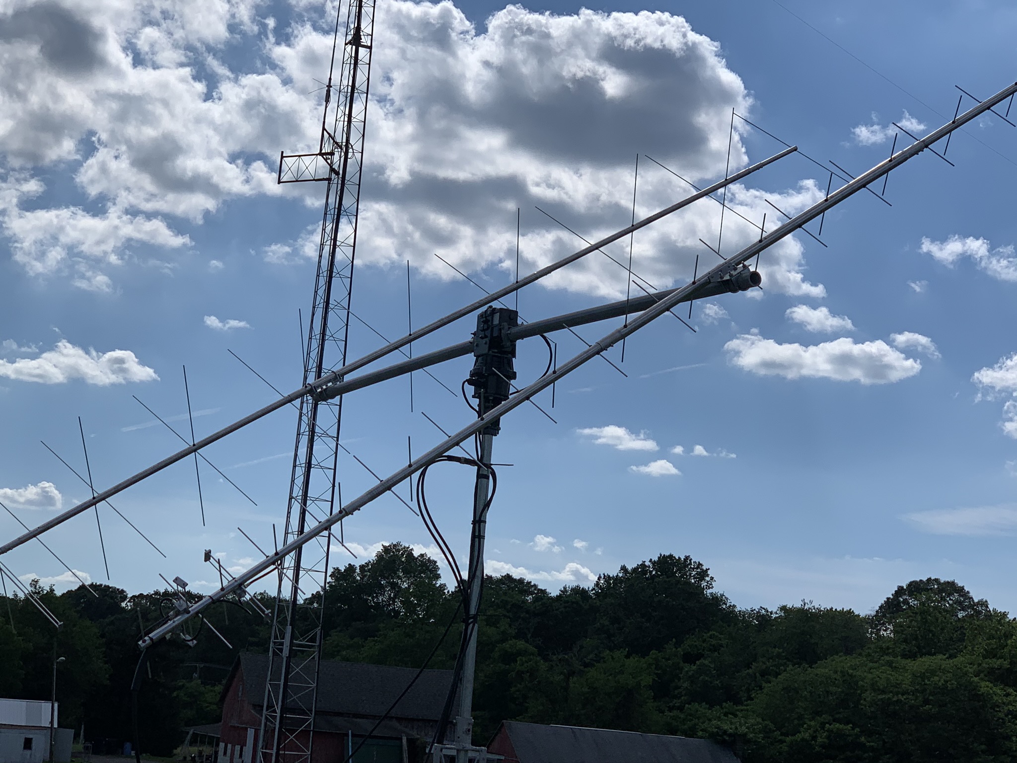
Figure 11-Look
at these beautiful antennas!


Informative
ReplyDeleteEarth station antennas